Teapotlabs BWLR1C is a wireless LoRa environmental sensor capable of sensing temperature, humidity, air pressure and air quality using the on-board BME680. This device is an updated to Teapotlabs BWLR1B, by using the an on-board antenna. By using an STM32WLE MCU, the device is capable of multi-year operation before changing the batteries
Teapotlabs BWLR1C is part of Teapot open-hardware project.
- The 1KM range is based on AERQ - Air Quality Monitoring design, but have not been tested on this device yet
- The position of the BME680 sensor on the board might not be the most efficient
- Change
SW4wiring from GND to 3V3, to allow booting to STM32WLE USART Bootloader. This enable the user to flash the RAK3172 module using STM32CubeProgrammer without ST-Link.
- RAK3172: An STM32WLE5CC module
- 3.3V only power/pin.
- 2uA Deep-Sleep
- BME680 for Environmental Sensing
- Switchable TX Power. 14 dBm(50mA) or 22 dBm(140mA) ( on 915MHz frequency )
- Supports LoRaWAN 1.0.3
- 1KM Range
- UART2 breakout for Arduino progamming
- SWD breakout for Mbed OS/STM32Cube programming
- SMA antenna connector
- CR2450 battery holder xor AA battery holder
- Capacitor ( optional to prolong CR2450 usage )
Based-on TI's White Paper, using coin-cell to draw short high-power pulses (~40mA) is possible, but will reduce the effective capacity of the battery. The White Paper proposed a solution to increase the effective capacity

PCB Render
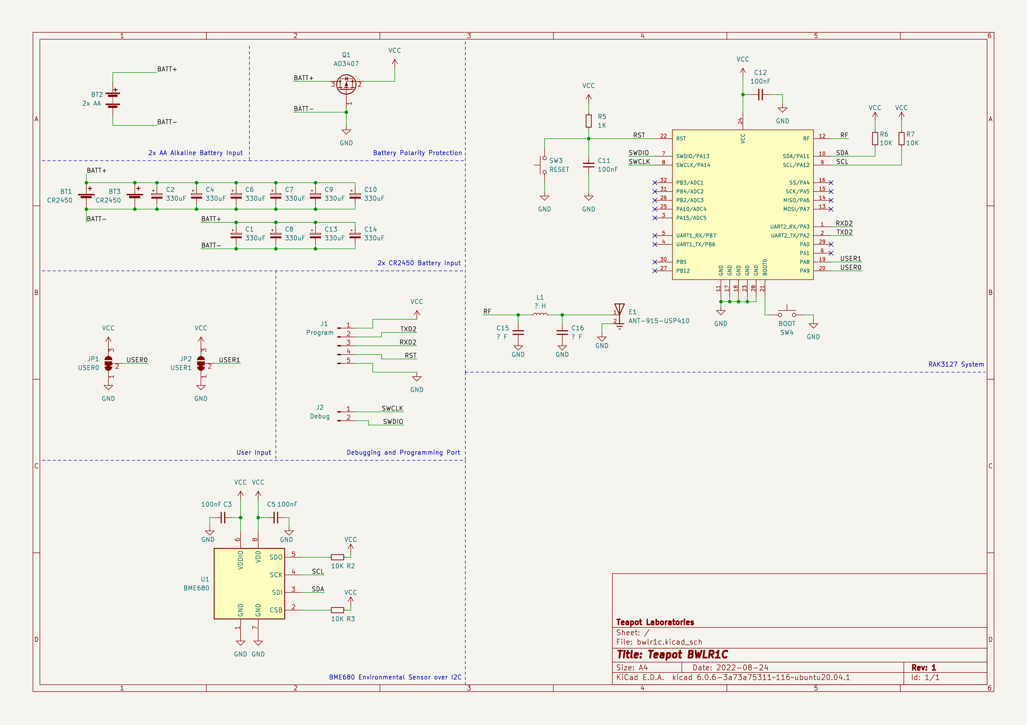
Built using KiCAD, the board is design to be as small as possible when operated using CR2450 coin-cell batteries
| Top Board | Bottom Board |
|---|---|
|
|
|
|


PCB Top and Bottom Layout

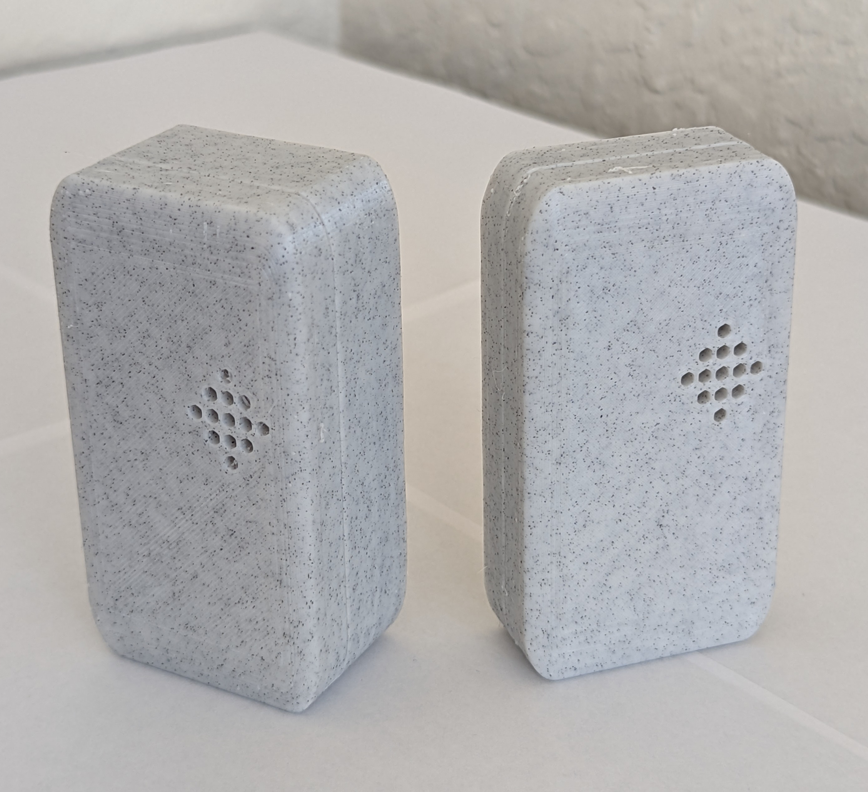
Built using TinkerCAD, the cases are available for the CR2450 variant and the AA variant, 3D printable with any generic 3D printer with/without suppport (depends on the orientation). The STL files are available here

Case Open
The case is design to be as small as possible with an additional magnets in the back to ease the placement of the sensor. The following are the list of material used at the time of testing:
- 4 piece of 8mm x 2mm neodymium magnet

Sensor Placement with Magnet
Power consumption and solar charging current are measured using Nordic PPK2. The following are the summary of the measurement:
- Transmit 14dBm: 443ms @ 47mA
- Deep-Sleep : 2 uA

Deep-Sleep

BME688 Measure and LoRa Transmit
More measurement can be found here
Most of the components are generic and can be bought from any electornics/semi-conductor distributor. RAK3172 is the only component available in RAKwireless store. The bill of materials can be downloaded here
⚠️ Be sure to buy the RAK3172 variant without IPEX to use the On-Board Antenna
| Id | Designator | Package | Quantity | Designation | Notes |
|---|---|---|---|---|---|
| 1 | C5,C12,C11,C3 | C_1206_3216Metric | 4 | 100nF | |
| 2 | SW4 | SW_SPST_Omron_B3FS-100xP | 1 | BOOT | |
| 3 | R7,R2,R3,R6 | R_1206_3216Metric | 4 | 10K | |
| 4 | C9,C8,C10,C2,C4,C13,C14,C6,C1,C7 | CP_EIA-3528-15_AVX-H | 10 | 330uF | Optional |
| 5 | R5 | R_1206_3216Metric | 1 | 1K | |
| 6 | E1 | XDCR_ANT-915-USP410 | 1 | ANT-915-USP410 | |
| 7 | SW3 | SW_SPST_Omron_B3FS-100xP | 1 | RESET | |
| 8 | U1 | BME680-PSON80P300X300X100-8N | 1 | BME680 | |
| 9 | U2 | RAK3172 | 1 | RAK3172 | |
| 10 | Q1 | SOT-23 | 1 | AO3407 | |
| 11 | BT3,BT1 | BatteryHolder_Keystone_3008_1x2450 | 2 | CR2450 | Mutual Exclusive with BT2 |
| 12 | BT2 | BatteryHolder_Keystone_2462_2xAA | 1 | 2x AA | Mutual Exclusive with BT3 and BT1 |
Programming the device can be done over the UART2 or SWD, available next to the On-board antenna. Out of the factory, the RAK3172 chip ships with an AT firmware that can be tested by connecting a USB-to-UART bridge to the UART2 port.
The following are some very good tutorial to start developing with the device:
- Communicating with the AT firmware
- Programming with Arduino
- Programming with STM32Cube
- Programming with MbedOS
For connecting to the UART2 port, use any USB-to-UART bridge module. In testing, the Sparkfun board is used for communication with AT firmware and programming over Arduino.
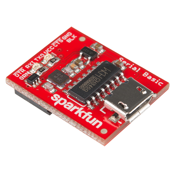
Sparkfun USB-to-UART Bridge
⚠️ Be sure to only use 3.3V module. Do not 5V module
For connecting to the SWD port, use ST-Link v2 in-circuit debugger and programmer from STM. In testing, ST-Link v2 clone will not work. The ST-Link v2 should atleast be reconizeable by the STM32CubeProgrammer. A cheap and alternative way to get an authorized ST-Link is to buy a Nucleo board, cut the top part which contain the ST-Link and use it as an external programmer.
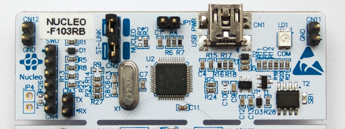
ST-Link v2 from a Nucleo Development Board
- https://www.radioshuttle.de/en/turtle-en/nucleo-st-link-interface-en/
- https://jeelabs.org/book/1547a/index.html
There are some issue, notes, and behavior that was discovered at the time of testing and development. The following are those discovery:
- Using Arduino RUI3 framework may introduce some-instability after programming. It is observed that by randomly power-cycling the board in-short interval after flashing, causes the board to hang in Boot mode. The fix is currently on the works.
The project won't be possible without the amazing work from people across the globe. The following are the reference to those awesome projects:
The product is open-source! However, some part of library used under src, might have it's own license. Please reach out or create a ticket to report any license violation.